First up is the construction of the base of the clock. The clock base is constructed of a front web frame that is mortise and tendon together, the front web frame is jointed to the base sides using a rabbeted tongue and grove joint. The sides of the base are half blind dovetailed to the bottom of the base..
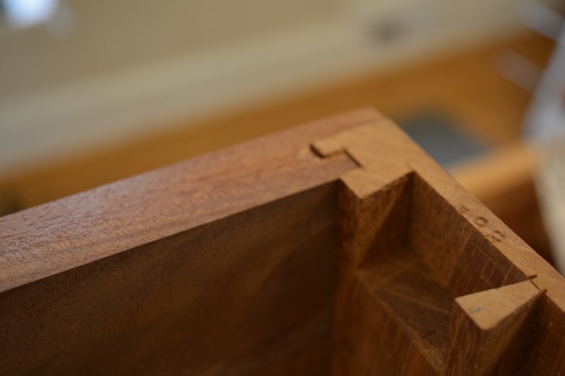
Here is the rabbeted tongue and grove joint, not sure if this would be a traditional joint used in the 18th century, but it made glue up a little easier. Additionally, the joint achieves the proper look of the intersection of the front and sides of the original clock. Pictures from the Met clearly shows a very thin front web frame (3/8″).
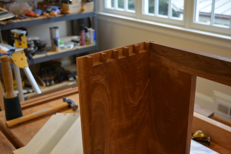
Since we are looking at the base front and sides from the bottom, we can see the half blind dovetail pins in view..
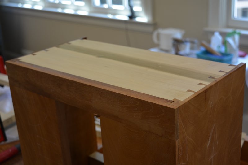
Finally with the base bottom glued to the case sides (as viewed from the bottom)..
The base molding is mitered and glued to a web frame attached to the base bottom (not shown), the base web frame is attached to the base bottom with elongated screw holes at the rear, to accommodate for expansion and contraction. The base bottom web frame allows the molding to be fully glued on all three sides of the web frame, without any fear of cross grain cracking of the main base. The molding simply overlaps the intersection of main part of the base and the web frame attached to the base bottom.
Finally the clock feet with be attached to the base bottom web frame…
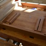
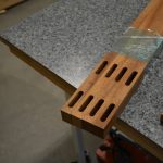
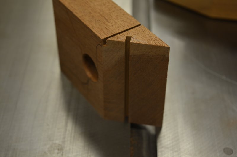
Now onto the feet, the front feet are mitered and receive a spline to reinforce the miter joint (viewed from bottom of foot).
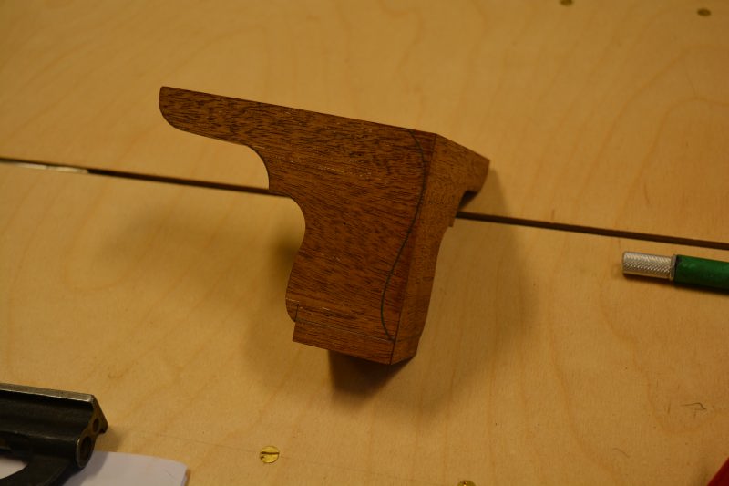
Here is a glued up front foot (right foot) with the side profile sawn, the foot profile has been traced on the front foot (see pencil). The foot profile will be bandsawn on both the front and side feet, then carving tools, files and cards scrapers will smooth the profiled front feet..
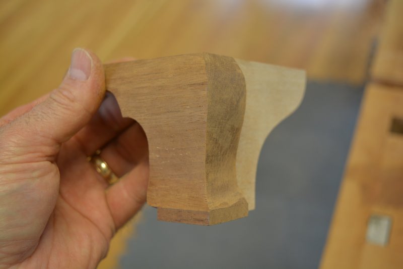
The rear foot are sliding dovetailed to a secondary back foot, here the mahogany left rear foot has had the side profile bandsawn and the secondary rear foot glued..
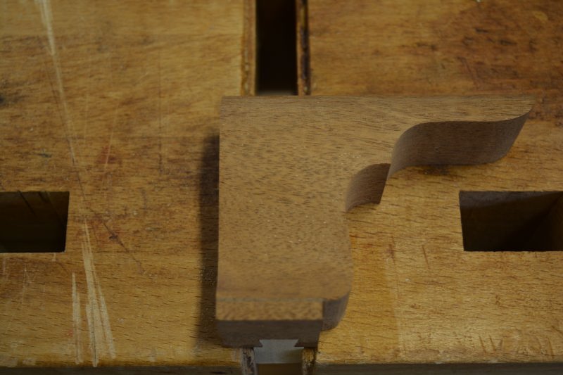
Finally a fully shaped right rear foot with the John Townsend trademark, of the back of the rear foot is fully shaped
Now we dry fitted the shaped feet to the clock base, next up is the front panel..
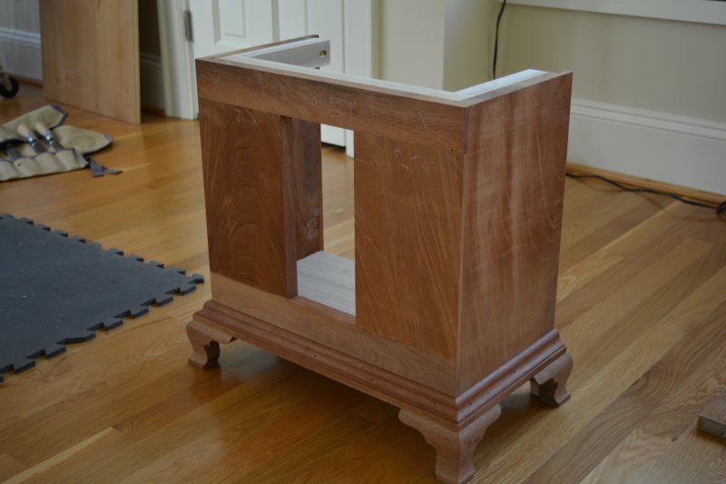
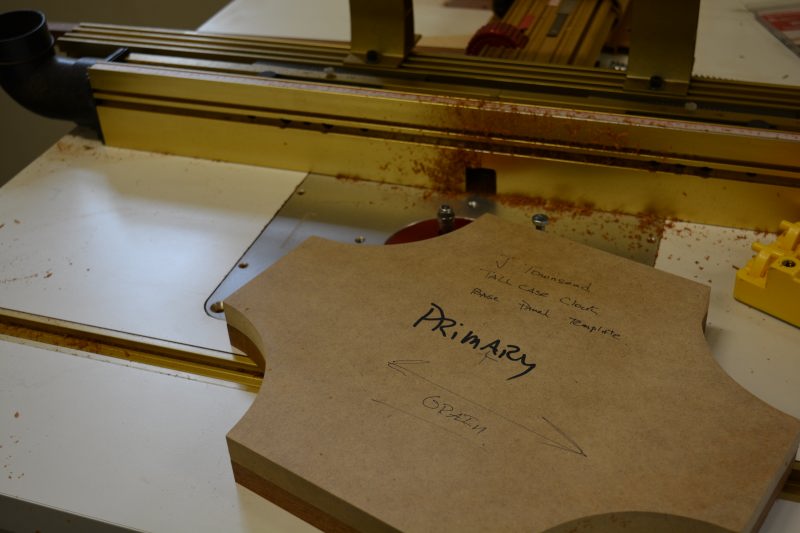
After milling the Mahogany for the base panel, the concave corners were roughly band sawn, then the panel was template routed.
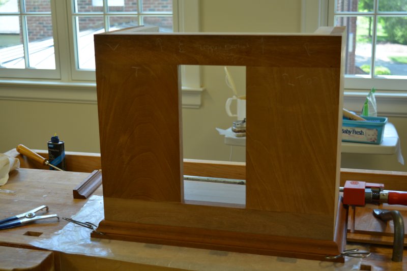
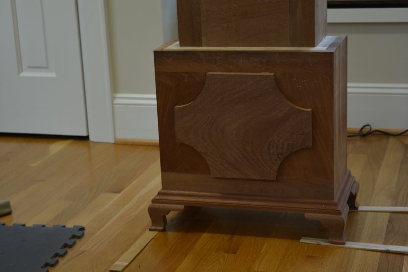
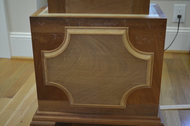
Finally we mount the panel to the base, now the panel molding needs to be milled, shaped and mitered to call the base panel completed..
The base construction could be considered finished after the completion of the panel molding that surrounds the raised center panel and the crown molding that finishes the intersection of the base and waist. One of the most challenging features of this clock will be the moldings, off the shelf router or shaper tooling is just not going to get the job done on this clock. The solution to the issue is hollows and rounds..
I bought a half set of even hollows and rounds built by Griffiths of Norwich England from a ‘reputable dealer’, the set is most likely from the early to mid 19th century. Little did I know the great condition ‘ready to use’ planes, were is such unusable state. Restoration of the planes has taken way more time than I had even imagined.I knew the sole of the planes would need tuning and the irons would more that likely need reprofiling to match the sole. Littled did I know, many of the planes were bowed along there length, pretty much rendering the plane useless as a car with a bent frame.
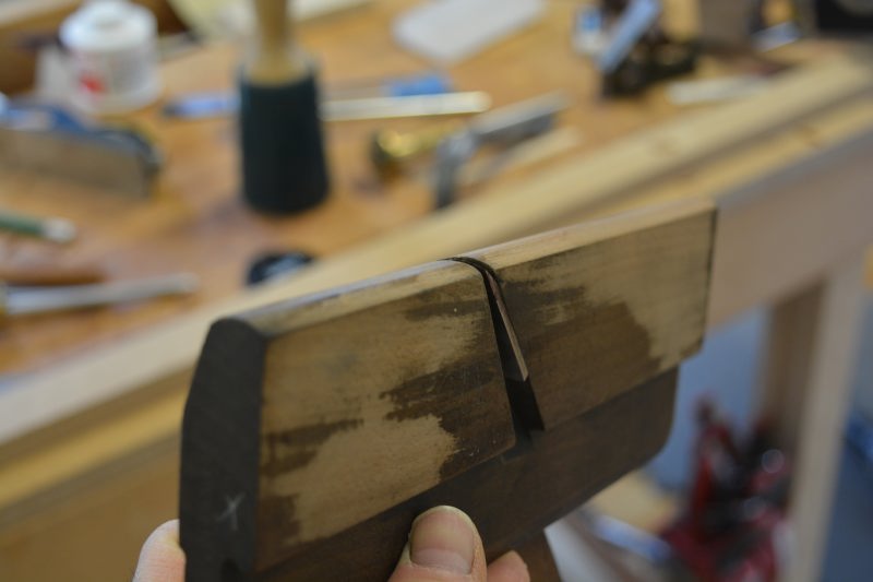
Below is a restored round..Doesn’t look pretty, but the works pretty nice now after its tune up.
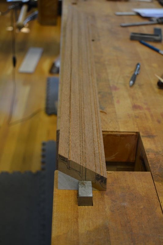
Now onto the straight panel molding.. We draw the side profile on a piece of Mahogany
Then a marking gauge is used to score layout lines on the raw molding..
The extraneous material is excavated with a rabbet (rebate) plane.
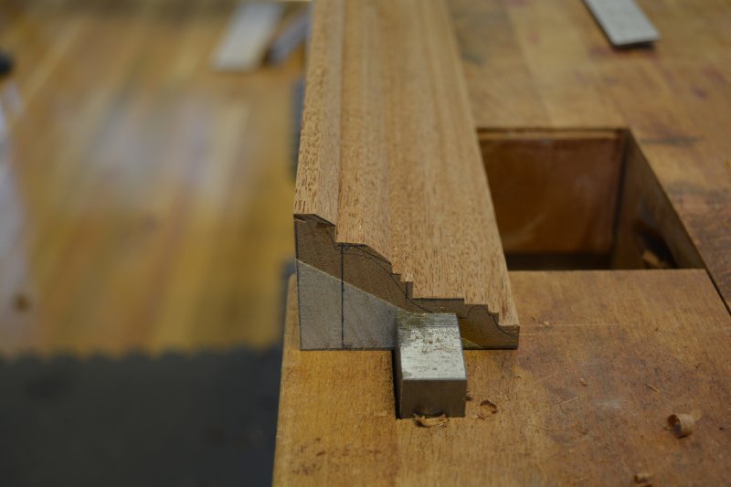
After a date with a #6 hollow and a #2 round, a #7 sweep carving gouge and vee tool and finally some scratch stock for that tiny bead in the front progress..
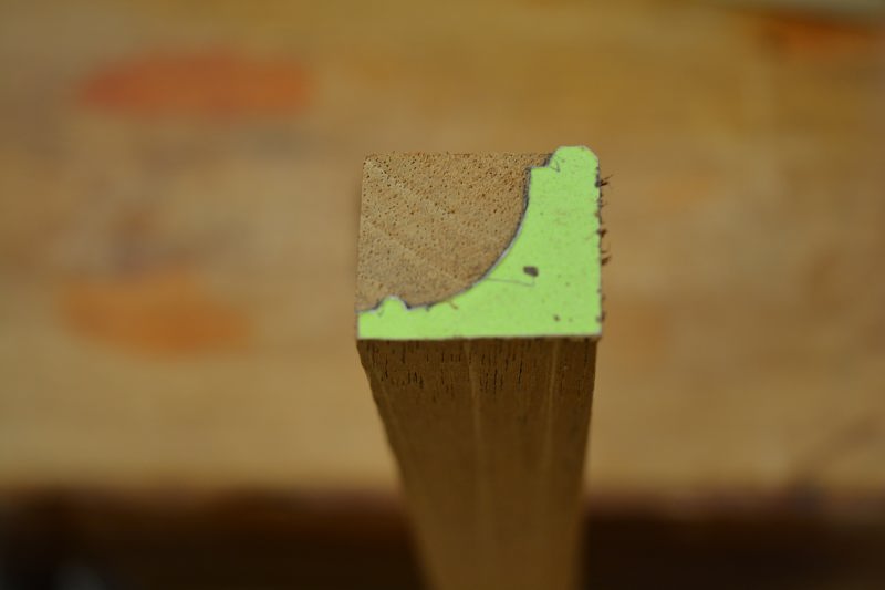
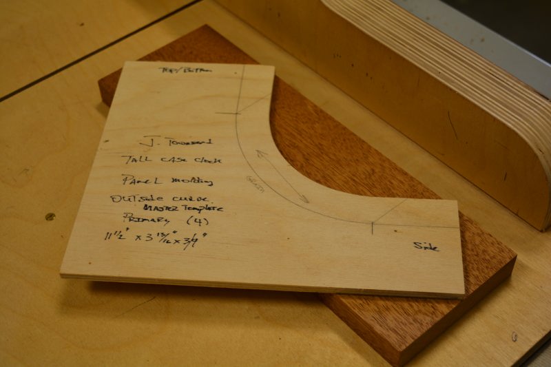
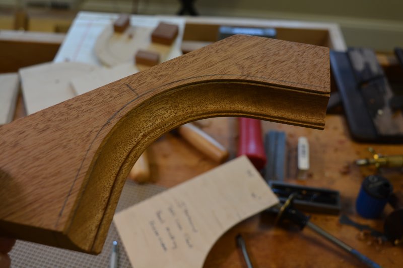
Now onto the curved panel molding pieces, the curved molding is made from a straight pieces of Mahogany, seen here with the template. The idea here is to try to get the grain running roughly parallel to the curve, for strength and to make the carving process somewhat easier.
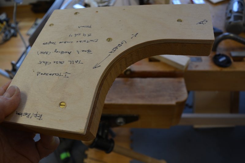
Here one of the curved molding pieces has been roughed out on the bandsaw and secured to a template for the next steps..
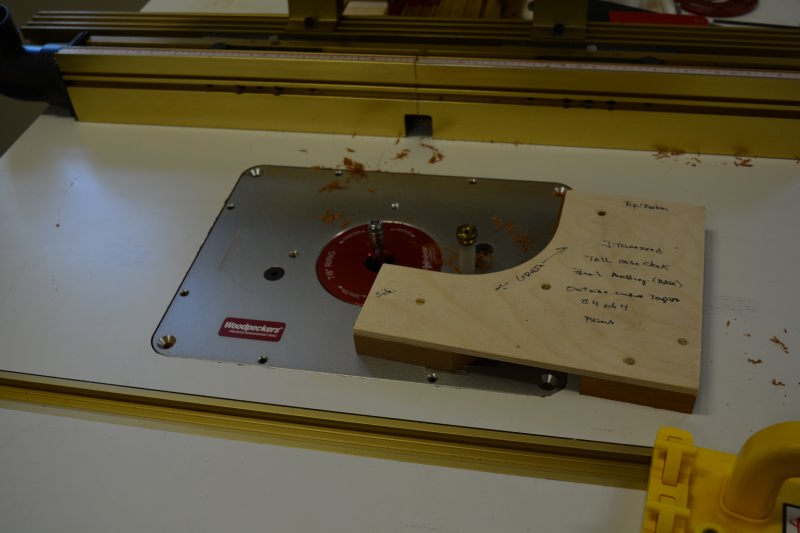
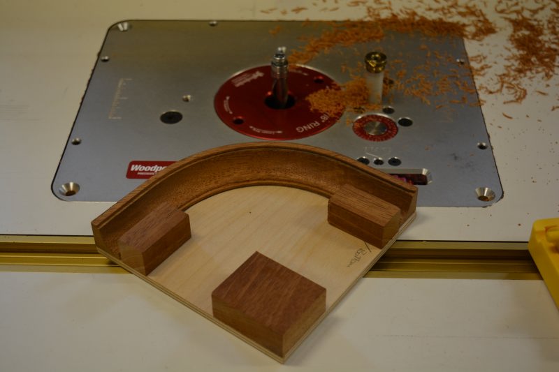
The bandsawn curve is template routed on the router table.
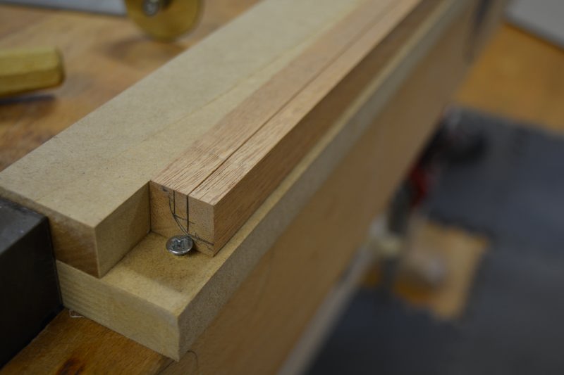
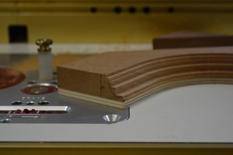
Then on the router table the various rebates and fillets are cut that will make the carving process easier
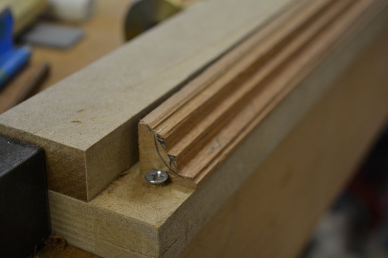
The first step is the curved panel molding has a date with a #7 sweep carving gouge..
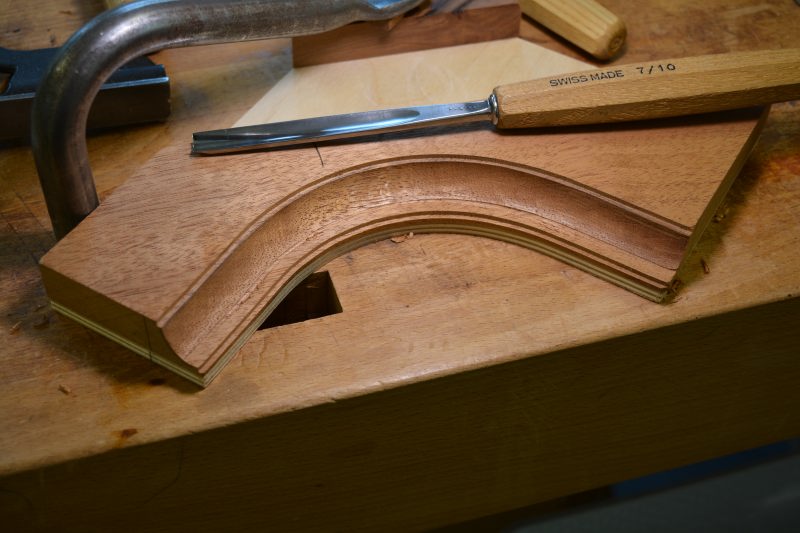
Next we mark out the area for the teeny tiny bead, remove the required material with a vee tool and the #7 gouges again…
That crazy teeny tiny bead was cut with a back bent #35 gouge, it was like torture
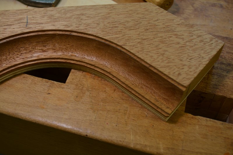
After removing the piece from the jig to hold it for carving, we mark out the rear curve with a template bandsaw the molding from the blank, then mount the piece to a new jig to template route the inside curve that will match the base panel. Next the small bead at the top of the molding needs to carved with a #35 gouge..
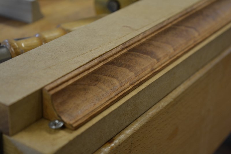
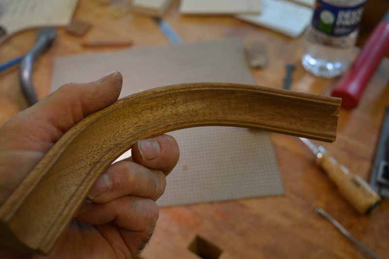
This is what a finished piece of the curved panel molding finally looks like after all the carving has been finished. Next the straight and curved moldings need to be mitered to surround the base panel, that should be a treat..
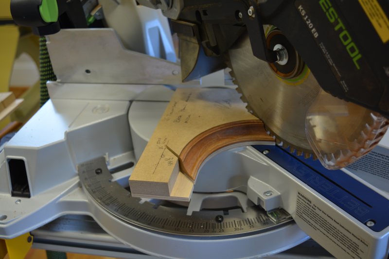
First we made two jigs for the chop saw, the most important jig is to hold that curved molding. Only get one chance to get this miter right
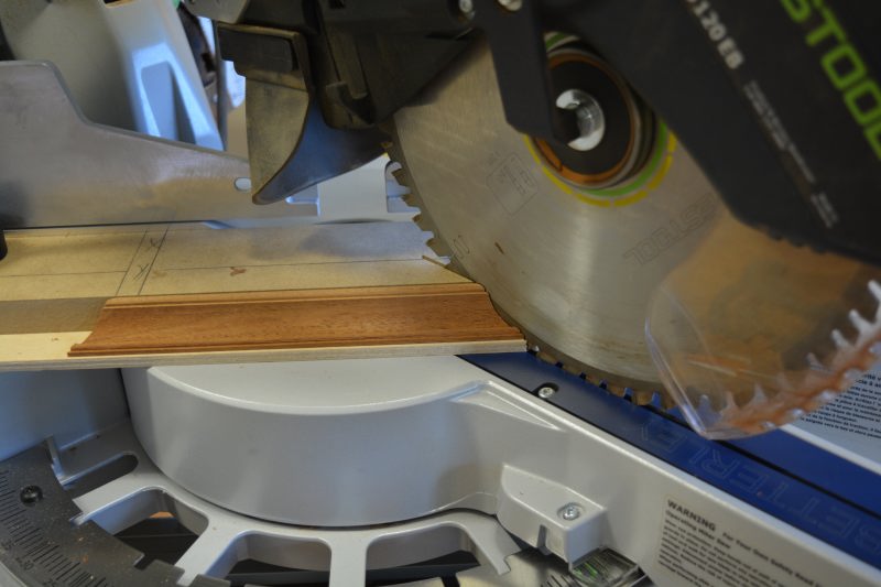
and jig for the straight molding, mostly to keep from blowing out the back and to keep the Kapex from being a missile launcher of small off cuts..
Finally after much fussing and tweaking with a super sharp block plane..
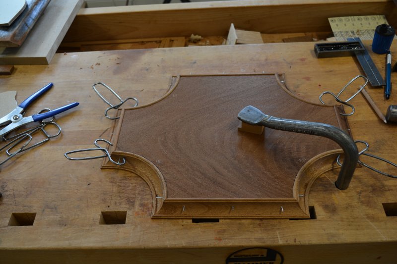
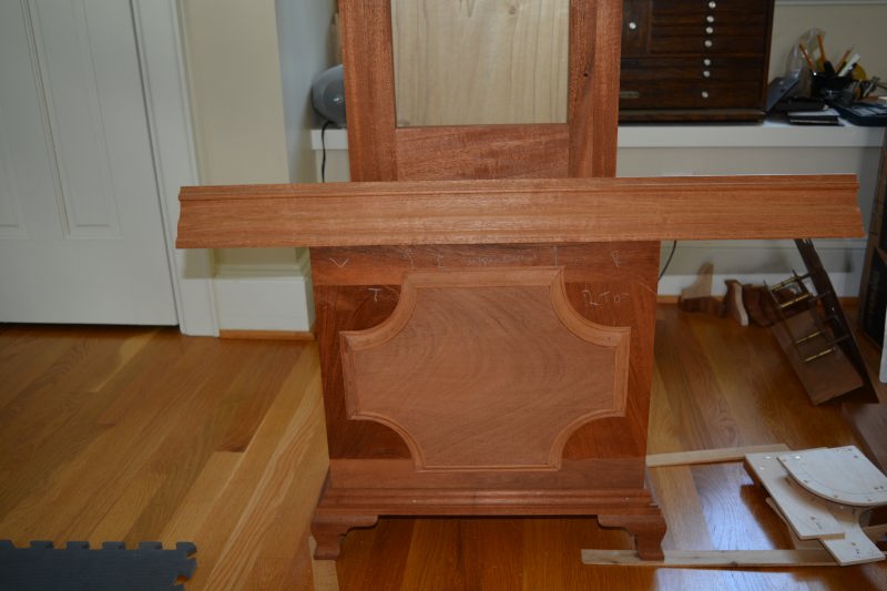
Finally mounted on the clock base, this panel was a beast..
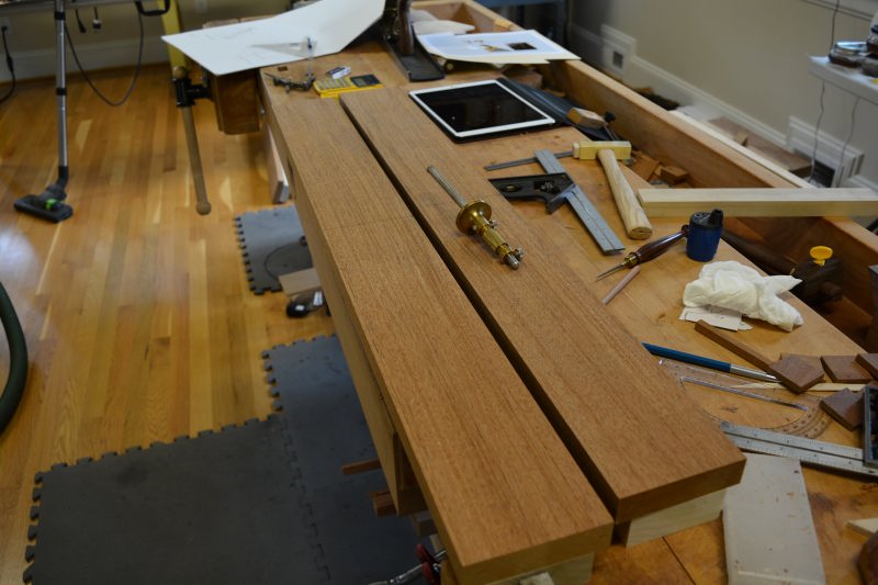
The last component that needs to be molded and installed is the base crown molding. The base crown, along with the waist crown and other components will be sourced from this 22″ wide x 10/4 thick slab of Mahogany
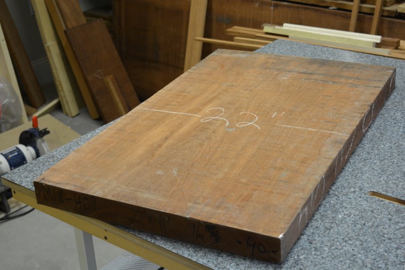
We rip off a two narrower widths of Mahogany from the slab and then resaw the pieces to yield four 1″ thick boards 1″ that will become the crown moldings
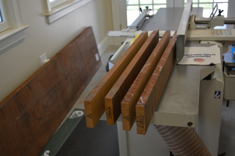
We are utilizing a technique that was rediscovered by Don McConnell and Larry Williams of Olde Street Tool, the original idea was published in the book Classical Revival Furniture Designs by Thomas Sheraton. Here we see the secondary wood (Poplar) has been glued to the back of the Mahogany to ‘pack out’ the back.
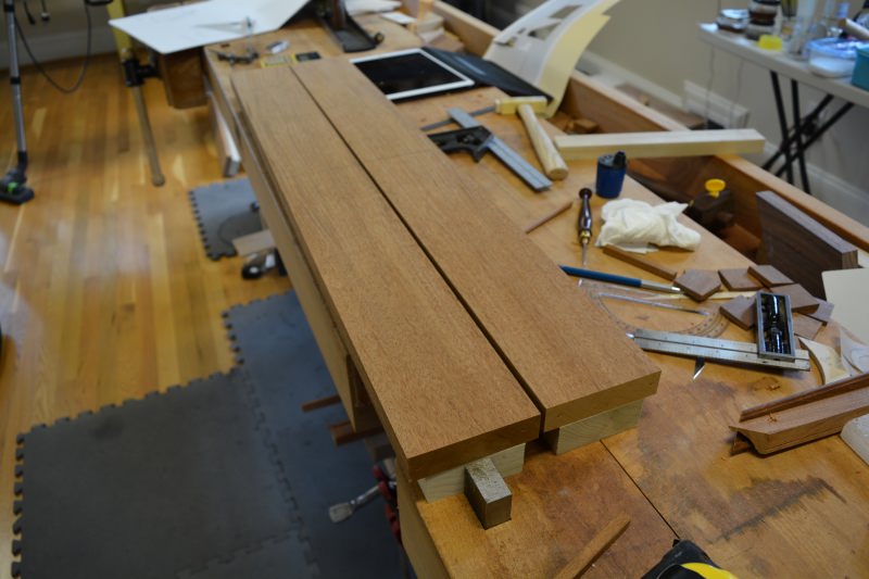
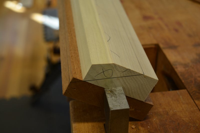
This step is the where the magic of Thomas Sheraton’s methodology begins. After the design of the molding has been laid out full scale, the layout is transferred to the board, then a marking gauge is used to mark transition points and fillets of the molding.
The spring angle of the molding gets transferred to the back of the molding with a sliding bevel gauge, the penciled area is removed with a jack plane.
This is what the spring angle looks like after the area is cleaned up with the jack and jointer planes..
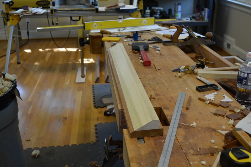
Next a plumb angle is planed ..
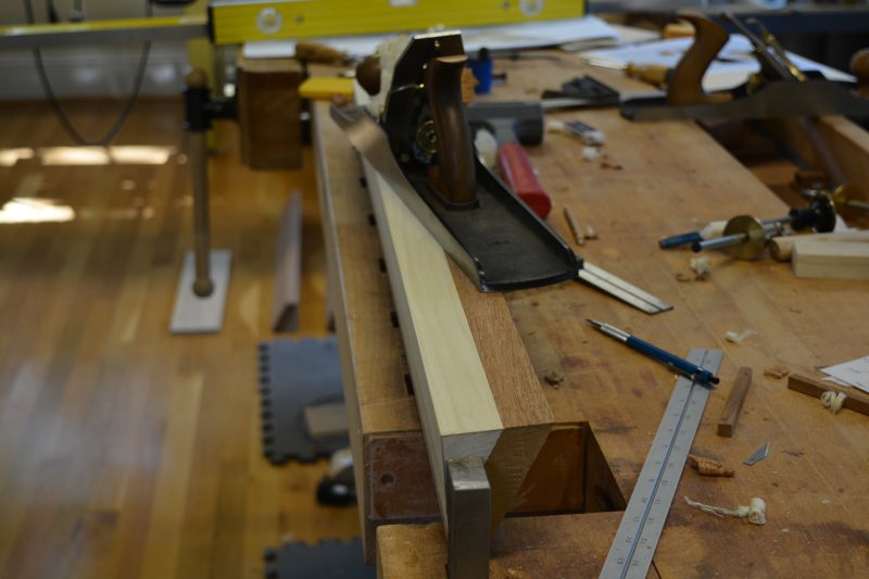
Here we see the profile of the molding drawn on the end of the stock. The gauge marks have been widened with a ‘snipes bill’ plane, the snipes bill plane creates a shoulder that a rabbet plane can ride against. Without this shoulder it would be next to impossible to create the molding.
Here we see after much wasting excess material from the molding blank with a rabbet plane. Next the molding plank is treated to many hollows, rounds and finally a side round plane to complete the molding.
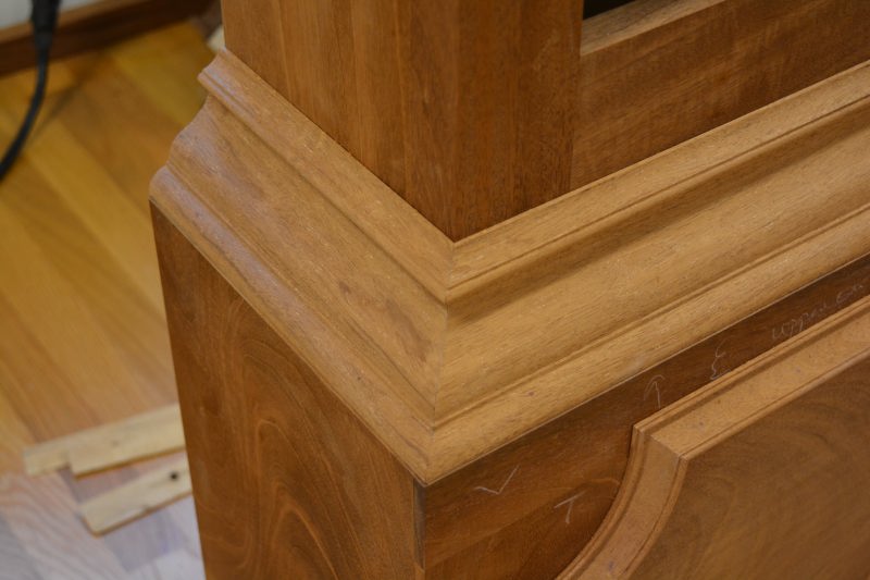
Finally, the completed base crown molding, next it needs to be mitered..
Finally mitered base crown molding, just needs a date with some glue now..
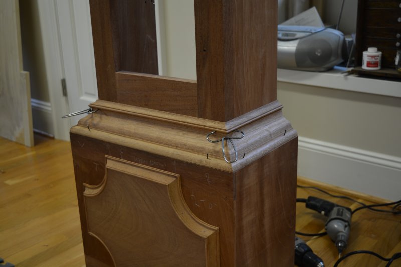
The completed base molding..The major construction of the base is now completed.